Chassis and motors Several versions available.
This section describes all mechanical parts required to build a CdoerBot
Chassis
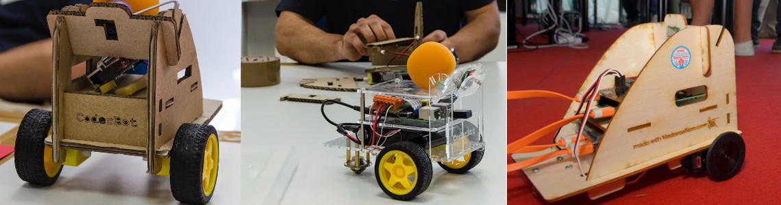
The chassis can be built using several materials: acrilic, wood, or corrugated cardboard.
For each material, a specific stencil is available. The stencil can be used to lasercut the chassis from a makerspace or lasercut service.
- Acrylic chassis - thickness: 3mm - motors: dc
- Wood chassis - thickness: 3mm - motors: servo
- Corrugated cardboard chassis - thickness: 6mm - motors: dc or servo
Motors
CoderBot can drive two kind of motors: dc or servo.
The choice of the motor type depends on the what activity the robot will be used mostly: servo are more precise although a little slower and more expensive tha dc.
Ball caster
We suggest to use a ball caster like this one, easy to find in an hardware store.
Screw and bolts
Screws M3x20 and bolts, M3x10 e M2x10 are needed to lock the camera.
Parts list
Parts are listed according to the chassis type.
Chassis: acrylic (plexiglass), motors: DC
This chassis is made from acrylic plastic. It can be transparent or coloured.
The transparent version let all the parts visible, the main disadvantage is the material is fragile and will not survive a fall from a table (tested).
It is specific for dc motors
| Component | Quantity | link |
|---|---|---|
| Chassis (plexyglass 3mm) | 1 | stencil for lasercut can be cut here |
| DC motors | 2 | link link |
| Wheels | 2 | link link |
| Ball caster | 1 | link |
| Spacer 10mm | 2 | link |
| Spacer 30mm | 7 | link |
| Spacer 5mm | 4 | link |
| Screws M3x5 | 2 | N/A |
| Screws M3x10 | 7 | N/A |
| Screws M2x10 | 4 | N/A |
Assembly
- Bind the motor to the chassis
- Bind the wheels to the motors
- Bind the ball caster to the chassis
- Put the motor controller board on the Raspberry PI
- Put the SD card on the Raspberry PI
- Put the wifi adapter in the Raspberry PI USB port
- Bind the two 30mm spacers to the chassis
- Bind the videocamera to his support
- Mount the lateral walls and the CoderBot logo tile to the main chassis
- Bind the videocamera to his support
- Bind the videocamera and his support to the chassis vertical parts
- Bind the videocamera and support to the main chassis
- Bind the Raspberry PI to the chassis
- Connect the videocamera to the Raspberry PI
- Connect the motors wires to the motor controller board
- Bind the "kill switch" in place
- Connect the "kill switch" to the motor control board
- Put the battery in the chassis
- Connect the battery to the motor controller and to the Raspberry PI, the CoderBot, will bootstrap.
[Coming soon: Assembly video tutorial]
Chassis Corrugated cardboard (6mm), motors: DC
This chassis is made of corrugated cardboard of 6mm thick.
The main advantage of this material is the low price, it can also be painted with pens or brushes.
Thanks to the joints and reduced use of screws, it can be assembled in minutes, even by children (initially with a tutor).
It is quite robust and resilient to falls, although it tends to flex and loose the mechanical properties over time.
| Component | Quantity | link |
|---|---|---|
| Chassis Corrugated cardboard (6mm) | 1 | stencil per laser can be cut here |
| DC motors | 2 | link link |
| Wheels | 2 | link link |
| Ball caster | 1 | link |
| Spacer 30mm male-female | 3 | link |
| Spacer 40mm male-female | 2 | link |
| Spacer 30mm female-female | 2 | link |
| Spacer 5mm | 2 | link |
| Screws M3x30 | 4 | N/A |
| Screws M3x5 | 3 | N/A |
| Screws M3x10 | 2 | N/A |
| Bolts M3 | 9 | N/A |
| Roundel M3 | 6 | N/A |
Assembly
- Mount the lateral walls and the CoderBot logo tile to the main chassis
- Bind the wheels to the motors
- Bind the motor to the chassis
- Bind the ball caster to the chassis
- Put the motor controller board on the Raspberry PI
- Put the SD card on the Raspberry PI
- Put the wifi adapter in the Raspberry PI USB port
- Bind the Raspberry PI to the chassis
- Bind the videocamera to his support
- Bind the Raspberry PI to the chassis
- Bind the videocamera and his support to the chassis vertical parts
- Bind the videocamera and support to the main chassis
- Connect the videocamera to the Raspberry PI
- Connect the motor wires to the motor controller board
- Bind the "kill switch" in place
- Connect the "kill switch to the motor control board
- Put the battery in the chassis
- Connect the battery to the motor controller and to the Raspberry PI, the CoderBot, will bootstrap.
[Coming soon: Assembly video tutorial]
Chassis wood, motors: servo
This chassis is made with a plywood (poplar or harder woods are ok) of 3mm thick.
Good compromise of robustness, economicity and durability. It can be painted, like the cardboard version.
Thanks to the joints and reduced use of screws, it can be assembled in minutes even by kids (initally wit a tutor).
It is quite resilient to falls.
It is designed to use servo motors. Wheels are the actual (large) wheel provied with the servo. They must be covered with rubber to avoid slides
| Component | Quantity | link |
|---|---|---|
| Chassis wood (plywood 3mm) | 1 | stencil per lasercut can be cut here |
| Servo motors | 2 | link link |
| Ball caster | 1 | link |
| Spacer 10mm | 3 | link |
| Spacer 5mm | 2 | link |
| Screw M3x30 | 4 | N/A |
| Screw M3x5 | 3 | N/A |
| Screw M3x10 | 2 | N/A |
| Bolts M3 | 9 | N/A |
| Bi-adhesive tape | 10cm | N/A |
Assembly
- Mount the lateral walls and the CoderBot logo tile to the main chassis
- Bind the motor to the chassis
- Bind the ball caster to the chassis
- Put the motor controller board on the Raspberry PI
- Put the SD card on the Raspberry PI
- Put the wifi adapter in the Raspberry PI USB port
- Bind the Raspberry PI to the chassis
- Bind the videocamera to his support
- Bind the Raspberry PI to the chassis
- Bind the videocamera and his support to the chassis vertical parts
- Bind the videocamera and support to the main chassis
- Connect the videocamera to the Raspberry PI
- Connect the motor wires to the motor controller board
- Bind the "kill switch" in place
- Connect the "kill switch to the motor control board
- Put the battery in the chassis
- Connect the battery to the motor controller and to the Raspberry PI, the CoderBot, will bootstrap.
[Coming soon: Assembly video tutorial]